
So as is evident from my other posts, I decided to scratch build myself a quadcopter, which I had to take myself from literally no understanding of these things at all to being able to build one that flies properly (which I did in fact manage to do). There was quite a lot of confusion thought this process, and I was not able to find a guide that really took me through all the basics in a useful way.
What is it?
The KK2 board is whats known as a flight controller, which is basically the brain of the quadcopter, its what takes the inputs from your controller and translates them into an output for the motors. Now its a bit more complex than this, it has gyros etc in it that will allow the copter to auto level when you lift off an input and basically will not allow you to do anything overly stupid with it.
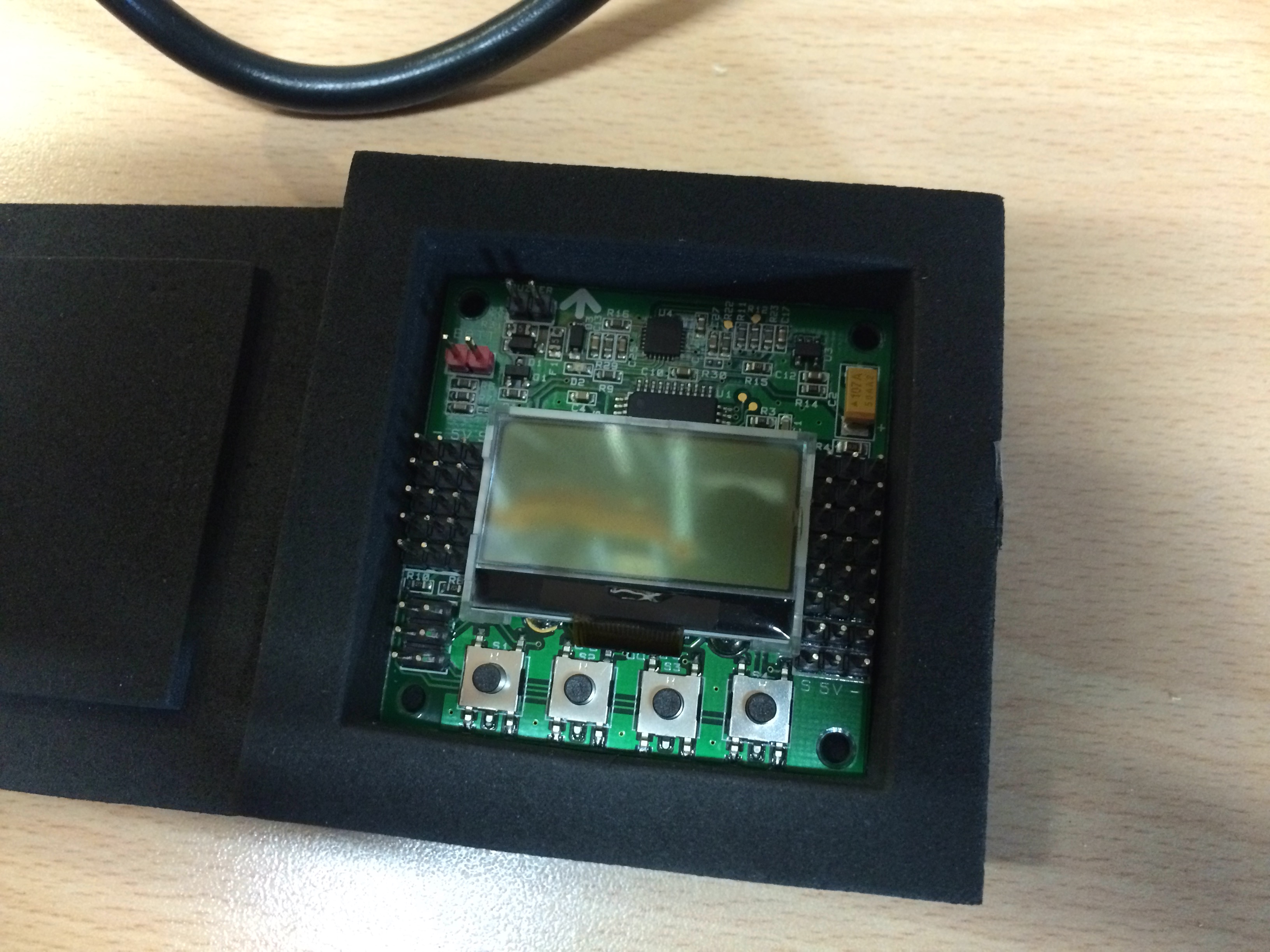
To me when I first looked at it, it looked quite complicated and hard to understand, but its actually very simple, and doesn’t take long to get a hold of what everything is. In terms of quadcopter use, the things you need to know is labelled on the diagram below
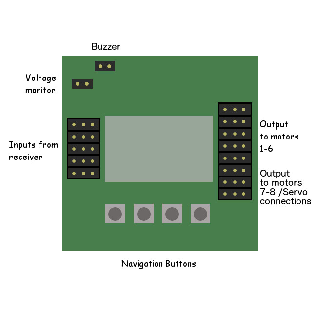
So just a brief explanation
Inputs – This will be the connection between the receiver from your controller and the flight controller. This flight controller has 5 slots for this, with each slot having a 0v, 5v and signal connection.
Voltage Monitor – Is exactly what it says, connect this onto the same power board or distributer the main battery is connected to, it will then display this voltage on the corner of the screen.
Buzzer – Again is exactly what it says, it will beep when the flight controller is in “Safe” mode and then sound for a longer time when the board is armed.
Outputs – This board has 8 outputs, which can connect between 3 to 8 motors, with the 3 pins being signal, 0v and 5v. This will then connect out to the ESC (Electronic speed controller) and then to the motor. It also has the ability to connect up to 6 motors and 2 outputs for servos for things like camera gimbals.
Navigation buttons – Used to navigate through the various options and menus on the screen.
Related items
There are two other main things that need to be connected to the flight controller, these are the receiver, and the electronic speed controllers (ESC)
ESC – This is what controls the main motors, it is directly connected to the battery of the aircraft, and then the motors, with a signal wire that will then connect to the flight controller. When you are shopping for an ESC, try and get one that has a built in BEC output, which is basically a 5v output. This is what will provide power to the actual flight controller.
Receiver – The receiver is basically the other end of the transmitter you hold in your hand, designs vary greatly but you can mix and match the channels to get it to do as you want. This will then connect in with the inputs to the flight controller.
Connecting it all up
Power – Power for this entire setup is usually a +5v output from an ESC, on my setup there are 4 of these, each with their own BEC. It is important to have only one of these actually powering the flight controller, so I have the power from 1 ESC connected to the output for motor 1 on the right hand side of the board, and although motors 2-4 are then connected to outputs 2-4, I have the +5v wire on the remaining 3 cut, and therefore not providing power. The power for the receiver on the other side is then passed through by the flight controller from the +5v, and so will pull power from this when it is connected and does not need its own separate supply. It is worth noting, Outputs 1-4 have the power connected together, and then 5-8 are connected together, so if you wish to pull the +5v from one of these they will need to have another supply going to them.
Receiver
Connections on the flight controller from the top to bottom are as follows
- Aileron
- Elevator
- Throttle
- Rudder
- Auxiliary – On this flight controller it is used to turn the self level on and off
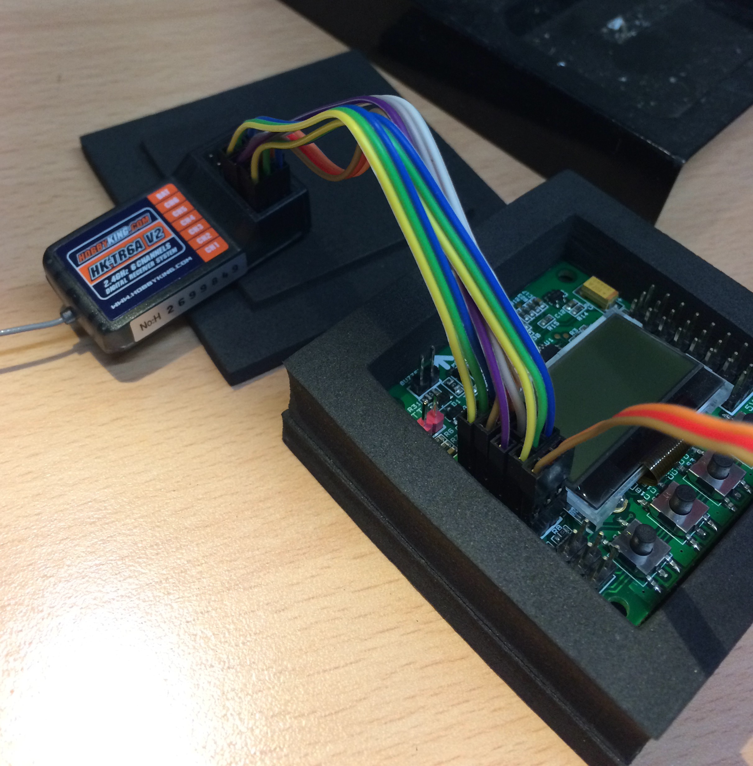
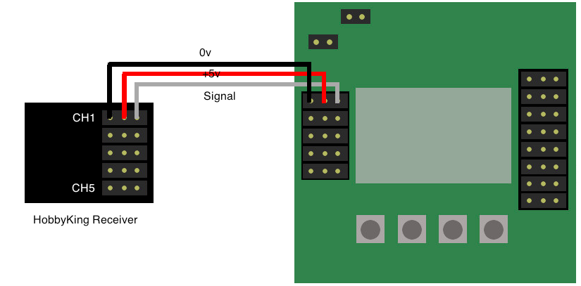
In my case, using a HobbyKing transmitter and receiver, the diagram below shows how it is connected, Channel 1-5 connected in the same way. Making sure each of the channels are in the correct place, which depends on your receiver.
Once the receiver is connected correctly it is then time to connect up the main motors, which is the pins on the right hand side of the board. Signal wire, like the reciever is is the pin closest to the screen, followed by +5v in the centre and 0v on the right.
Buzzer, which is used for alarms is connected to the 2 pins top left of the board, and the voltage input (in my case taken from the power distributer board for the ESCs) connected to the one just below and to the left.
This should then be all of the connections you need to get you up and running. The settings on the flight controller itself are usually set by default quite well and will get you off the ground. I will do a guide in the future in regards to tuning.
Thanks for reading 🙂

Thanks for the guide!
LikeLike
Getting started late with these. Thanks for posting this, it explains a lot.
LikeLike
hi.im building my 1st quad a kk260 which i plan to fly mostly acro style.do u think that this fc is appropraite .im not good at setup from a pc. thanks
LikeLike
i am building a quad using the flysky 6 channel receiver and the kk2 .
And i can’t figure out how to connect those both . i seriously need some guidance plz help…………….
LikeLike
From a quick google I think your reciever is a very similar setup to the one I have in a diagram above. Just need to make sure your pin outs are in the same order. Should be able to find some sort of diagram for it online!
LikeLike